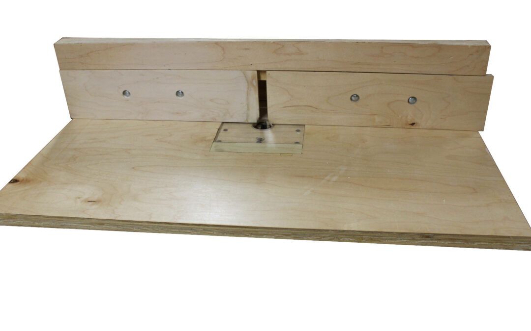
Bulding a DIY Router Table

Bulding a DIY Router Table


.DIY Router table Build-FinishedOver the years I’ve had a lot of router tables. I’m not a big fan of commercial tabletop router tables, they always seem to be too small. there are quite a few manufactured router tables on the market, Rockler is a very popular model and they do have a nice aluminum plate or a Phenolic plate that you can buy to fit into your table. Ultimately, I have found that Building a DIY Router Table is the most cost effective solution that will give you the best product for your needs.
 

Early on in my Woodworking journey, I read an article from Wood magazine (This link is an upgraded model) that provided a very basic router table that clamped to the top of one of my work tables. This DIY router table had slots cut in the side of the table to adjust the fence back and forth. This was a very problematic adjustment. I decided that this time around I would add some dust collection and change the fence adjustment to run on T-tracks.


Finding a DIY Router Table Plan
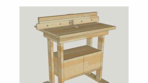
 

Router Table Plan ViewThere are hundreds of plans for Router Tables available on the internet.  Some plans need to be purchased but others are free for the asking. I often use Sketchup to design jigs and fixtures so the first place I looked was in the Sketchup 3D Warehouse.  Even here the possibilities are hard to narrow down.


I chose a basic Router Table plan (https://3dwarehouse.sketchup.com/model/u716d971c-62b4-4f3a-889b-ae763b3e4f64/router-table) and downloaded it.  I didn’t need a base as I was simply going to clamp it to my Woodworking Work Table while in use and store it away under the table when not in use. I was only interested in the major dimensions as I have used a homemade Router Table for years and just wanted a bit of a refresher.


Features of the Router Table


There isn’t a lot that needs to be worked out with a basic Router Table.  There needs to be a stiff top and the Router needs a place to mount to the underside of the table. A plate that is adjustable needs to be mounted above the Router into the top of the table.  This plate needs to be precisely flush with the top of the table.


The table needs to have a fence mounted to it and the fence needs to be precisely 90 degrees to the top of the table.


I’ve seen two main designs for fence adjustment.  One has a pair of hold-downs on the back of the fence.  The fence adjusts forward and back in a parallel path to the edges of the table. The second design has a single adjustable end and a pivot end.  Adjustment is in an arc around the pivoting end. Either of these arrangements work quite well. It is mostly a matter of what you are comfortable with.


This video from Izzy Swan shows how you can build a quick disposable Router table with the pivoting fence.  I didn’t want to go this basic and I wanted something that would hold up to hard use.


For my particular Router Table, I’m going to add a couple of moveable fronts to the fence and mount a 4” port on the back of the fence to accept my dust collection hose. The moveable front pieces will allow me to adjust the space around the Router Bit to accommodate different sized bits and still keep the workpiece supported. I can add more T-track at a later time or cut a miter slot into the table if I find that I need that capability.  For now, I’m going to keep it simple and quick.


Building the Router Tabletop


The Sketchup drawing that I downloaded shows a tabletop that is two laminated pieces of ¾” plywood. I didn’t think that a 1 ½” tabletop was necessary so I opted to use ½” plywood.  I think this works fine. I’ve read where it is important that the tabletop doesn’t flex but I haven’t noticed that this reduction is a problem.


I cut two pieces of ½” Maple plywood to 37” by 24” and laminated them together with Titebond carpenter’s glue.  I lined up the two pieces as well as possible but still had a bit of slippage. A quick pass with a flush-cut router bit evened up the edges.  They aren’t precisely square but on a router table, a perfectly square cut isn’t necessary.


Adding T-Track for the Fence Adjustment


Next, I needed to cut two channels perpendicular to the back edge of the table for T-Track.  The T-Track that I bought required a ¾” wide slot ½” deep. Fortunately, I have a Router, this makes it very easy to cut a slot for these T-Tracks.


To cut these slots into the table, I set up 3 pieces of scrap plywood with straight edges.  Two of the pieces guide the Router in a straight line that is set perpendicular to the back edge and the third one fills the gap between the first two to act as a stop for the router.  Careful measurement ensured that the center of the router bit was in the right place and a 3-inch spacer that is the same size as my Router base was used to check the spacing. I clamped this jig to the table and screwed the length stop in place to the guide rail pieces. I used a ¾” router bit and made two passes each ¼” deep.    Using a hacksaw, I cut the T-Track to length and glued and screwed the pieces into the slots.
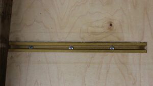
 

Router Table T-Track


Mounting the Router In the Table


To mount the Router into the tabletop, I needed to cut a recess into the underside of the top.  I suppose that the Router could be mounted directly to the bottom of the top but it is an inch thick and limits the amount of travel that the bit has for doing the actual work.  I chose to make the recess round and the diameter of the Router Base.  


To cut the recess, I again turned to the Router with a straight bit (I used a ½ inch bit).  I have replaced the bottom plate of my Router with a sheet of plexiglass so that the bit is easier to see. I just hand routed the recess in two passes of a ¼” each.


I set the Router base into the recess making sure that it was oriented so that I could reach the adjustment release.  On my Router (Porter Cable 690- The Porter Cable 690LR is the replacement model now- get the fixed base /Plunge base combo if you can afford it) the adjustment is a large wing nut.  Mounting it to the front of the Table allows me to release the Router and adjust the height easily.  


Router Table Router Recess


On my last Router table, I mistakenly oriented the release on the back and spent a lot of time trying to reach the adjuster around various obstructions.


I marked the location of the screw holes and drilled a pilot hole for each of the 3 mounting screws.  From the top, I countersank these holes to accept a flat head screw for mounting to the table. I mounted the Router base to the bottom of the table and with a ¼” bit rotated the Router into the base with it running until the bit drilled through the top.  Then I unmounted the Router from the base and using a hole saw, drilled a 2” hole in the tabletop using the routed hole as a guide for the hole saw. 


I have some large panel raising bits but this should be a good size for most of what I need it for.  I did cut another recess in the top to fit the router sub-base that I use for my handheld routing. This sub-base is a ¼ inch piece of plexiglass with mounting holes recessed into it.  It fits either on the router base directly or into the recess in the top of the router table. I added 4 flat head screws into the corner of the recess in the router table to adjust the plexiglass to be flush with the top of the table.


DIY Router Table-Fence


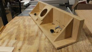
A Do it Yourself Router Table Fence can be as simple as a straight board clamped to the table or it can be a precision-ground steel fence with grooves for accessories and a miter slot.  I chose to make a simple fence with a precise right angle and sliding front pieces to focus the air around the router bit and support the workpiece on each side of the cutter head. On the back is a 4” port to accept my dust collection hose.


For the fence, I needed to have a stable surface.  I used ¾ inch Maple plywood for this (Birch Plywood is the preferred material but for some reason, it isn’t available in this area). This higher-end plywood has 3 laminations and no voids.  This makes for a strong and stable surface.


For my design, I needed a base, some 90-degree gussets (4), a front, a top cover, and two sliding front covers. The Base and Front parts are 6 inches wide and 39 inches long(The width of my tabletop) The Base has two ¼” holes lined up with the T-Track in the Tabletop and I cut a semicircular relief out at the center (2 inches wide and 2 inches deep) to allow the dust from the Router to be pulled in to the dust collection port.  The front has 4 slots cut to allow the sliding front covers to be adjustable.


Router Table Adjustment Slots


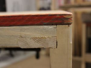
I assembled the front to the base and clamped the 90-degree gussets to the front and base.  The Front piece goes in front of the base and not on top. This makes the front piece sit on top of the tabletop.  When you cut the 90-degree gussets, cut a relief in the top and back so that I have a place to clamp the parts. I didn’t do this and gluing was a real pain. I had to clamp an angle bracket and to the front and base.  I used lots of clamps and had to wait until the glue set to move on to the next one. Make sure that while the glue is setting, the base and front are precisely 90 degrees from each other.  The gussets should hold this angle but verify it just the same.


.When the glue is dry, glue a 3-inch piece on the front top of the front of the base.  Space this piece 3 inches up from the bottom with the sliding front pieces. Leave enough room so that the lower pieces will slide but be guided by the top piece.


Mark the back of the lower sliding pieces at the center of the slots that you cut into the Front piece and drill holes for ¼” Carriage Bolts.  Drill a small pilot hole first, then using a Forstner bit, drill a recess in the front so that the head of the Carriage bolt is recessed. Then finish drilling the hole for the shaft of the Carriage Bolt from the front of the sliding pieces.  This will give you maximum travel from the sliding front pieces.
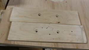
 

Router Table-Sliding Front pieces


The last bit of work that needs to be done is the dust collection port.  One piece is attached to the two center supports. A 4” hole is drilled or cut out to accept the hose from the dust collector.  A second piece closes up the back of the chamber to direct the dust up into the collector hose.  
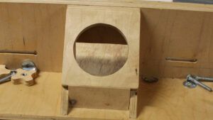
 

Router Table Dust Collection Port


Router Table Fence


Putting Together the DIY Router Table


To assemble the Router Table, mount the fixed base of the Router into the recess in the bottom of the table.  Screw through the top and verify that the screw heads are recessed below the plane of the top. Insert the carriage bolts through the front of the sliding front pieces of the fence and thread on a handle for each bolt.  Insert the ¼” machine bolts into the T-Track and fit the bottom of the fence over the bolts, then secure these with a nut or handle to tighten the fence to the table.

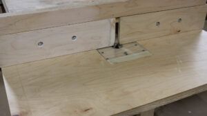
 

Router Table-Under Table Mounting


Router Table Completed


Clamp the table onto a work surface and insert the Router into the fixed base attached to the bottom of the table.  Ready to go!


Router Table - Clamped and Assembled


DIY Router Table First Test Run


My neighbor was working on his daughter’s house.  He had a large amount of baseboard that he needed to install and a shed full of Red Oak planking.  He wanted to create a round-over on the top of the planks so that he didn’t need to add a quarter round to the top of each plank.


With the Router Table, it was quite simple to create this round-over.


Step one was to install the Router Table on my mobil work table and set up an out-feed roller stand near the Router.  Then, connect the dust collection to the port and install a 1/4″ round-over bit into the Router.   Next, we adjusted the height of the bit to round the edge of each board.  This just removed the corner, a second pass will deepen the first cut and create the profile that he wanted with a 1/8″ reveal on the profiled edge.
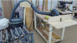
 

DIY Router Table-First Run


Then it was time to don the ear protection and dust masks to keep us safe, fire up the dust collector and start routing the profile.  After the second pass, we called it a successful test run.
 

Router Table Test Run Profile


Overall, I was pretty pleased with how well building this DIY Router table went. I will probably do a few enhancements to this table in the future.  It may be nice to have a miter slot near the front of the table to help with keeping tenon joints square to the end of the workpiece.  I have used square back-up blocks for this operation but it would be more stable and precise with a jig installed in a miter slot.


Every project in the shop is a work in progress.  If I need to modify or enhance one of my tools, I won’t hesitate to make the changes.


I’d love to get your feedback on this project.  Feel free to comment below and let me know how you have enjoyed this post and if you have tried something like it in your shop.

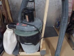


Small Woodshop Dust Collection System

In my woodworking workshop, I have several large machines that generate dust.  I have a Table Saw, a Radial Arm Saw, A large Bandsaw, a small Bandsaw, a 12” Planer, and a Router table. There is a King scrollsaw that my partner uses and I do a considerable amount of sanding and planing as well as generate dust from Circular Saws, a Drill Press, and my Lathe.  I am in need of a small woodshop dust collection system that will get a handle on all of this dust created by my woodworking activities.

How Does a Dust Collection System Work?

A dust collection system generates a high-velocity stream of air to draw the dust and small particles into a hose.  The hose deposits this dust into a chamber where the dust is removed from the air.

Many Woodshops will have a central dust collection system that is connected to the large machines by dust collection conduit.  Other Woodshops will have dedicated dust collection machines for each tool. Some small Woodshops will have a system that is portable and can be moved to the location that is generating the dust where it is being created.

I have implemented a combination of these solutions.  A three-pronged approach is the best solution. I have a small single-stage dust collector near the scroll saw and drum sander, and a portable 2 stage dust collector for the larger tools. A shop vac with pre-separator services the small tools.  Overhead a box fan will collect the fine dust through a standard home air filter and then blows out through another electrostatic filter.  

How Much Dust Collection Do I Need?

As I mentioned above, I have some large dust-generating machines. Each of these has a specific need to remove the dust it generates.

How Much CFM Do I Need for Dust Collection? 

Machine CFM Requirements
Table Saw 10” 300-400
Band Saw 16” 350-400
Planer- 12” 500
Disc sander 300-350
Belt Sander 550-600
Drill Press 300
Scroll Saw 300-350
Router (Table Mounted) 200
Band Saw- 4” 150


For my largest machine, I need about 500-600 CFM.  I don’t know of a shop vac that will generate this kind of volume (In general, a shop vac generates about 165 CFM)so, I need to have some sort of dust collection system that can generate this volume of air.  A small impeller based collection system with a 4” hose and a filter are what I need.

What do the Specifications for Dust Collectors Mean?

There are two main specifications that are used when discussing Dust Collection systems.  These are CFM and FPM.

CFM stands for Cubic Feet per minute and is the measurement of how much air can flow through the system. CFM is determined by the velocity of the air and the size of the pipe that it is flowing through.  

FPM or Feet per Minute is a measurement of the speed of the airflow.

Higher velocity air has more carrying power for the dust generated at the machines but this typically comes with a smaller hose and less overall volume.

Can a Shop-vac be Used for Dust Collection?

A shop vac can be used for a light-duty dust collection system but only for small particles and small amounts of dust.  I do use my shop vac to collect dust from my 4” Bandsaw. I also place a wide end on the hose and keep it near my random orbit sander when I’m using that to gather the fine dust that is generated and keep it away from my lungs(with a dust mask).

For larger machines and most cutting operations, the shop vac doesn’t pull enough volume for adequate dust collection.

What is a 2-Stage Dust Collector?

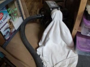
A 2-stage dust collector is a single-stage impeller and filter with a chip separator on the input side of the dust collector.  The chip separator is typically a cyclone separator but may be a Thein baffle. The separator keeps the large chips and coarse dust out of the impeller and lets the fine dust pass through and get caught by the filter bag.

Portable Dust Collector

What is the Advantage of a Cyclone Dust Collector?

Removing the larger particles from your dust collection stream does two things.  First and foremost, it increases the life of your filter bag and the impeller/fan works less hard and pulls less power to maintain its speed.   It also allows more time between bag cleaning or filter replacement. This is often a very dusty operation and puts lots of fine particles back into the air of your shop.  The bags and filters are somewhat expensive and any reduction in replacement cost is a good thing.

A much cleaner operation is emptying the coarse dust and chips that are collected by the cyclone.  Less fine particulates will be generated to get back into the air in your shop and perhaps get into your lungs.

If you have a cyclone installed before your shop vacuum, you may increase the life of the vacuum itself.  The fan in the shop vacuum draws less power through a clean filter.

What is a Thien Baffle Dust Collector?

The Thein baffle system is a plywood sheet that is sized to fit inside the collection bucket,  It has a slot cut around 240 degrees of the edge that allows dust to fall below the baffle into the collection area.  Incoming air is directed around the outside of the collection bucket. Friction against the outside of the bucket slows down the dust where it falls below the baffle into an area of less air turbulence.  This allows the dust to settle.

Thien Baffle systems don’t appear to be available for purchase.  You need to put on your DIY hat and fabricate one for yourself. There are lots of YouTube videos and forums that discuss the design and implementation of the Thien Baffle system.

To get you started, here’s a link from the JP Thien website that explains how the baffle goes together.(http://www.jpthien.com/cy.htm).

Clearing the Air in Your Shop

What size is wood dust?

 Wood Dust ranges in size from 1 micron to up to 90 microns.  Above this size, the wood dust is referred to as chips. Removing the chips does nothing for the smallest particles that can clog your lungs. Most filter bags that come with dust collection systems will filter down to 2-3 microns.  Particles smaller than the filter can handle should be removed by an air cleaner that pulls air through a set of filters.

How long does wood dust stay in the air?

A significant amount of wood dust smaller than 10 microns can be suspended in the air for up to 30 minutes by the simple act of sweeping your shop. 

Using Saws and sanders can generate a lot of dust.  Place dust collection as close to your equipment as possible.  Many shops will create a ducting system that pulls the dust to a central collector.  The ductwork creates significant losses in the system and makes it necessary to oversize the system.  4” hoses and ductwork should be the minimum size with 6-inch being the optimal size. 6-inch ductwork will require at least a 2 HP motor to pull sufficient volumes of air.

 Dust collection and air filtration is a must!

What do I Need to Implement for Dust Collection?

In my shop, I settled on a portable dust collection unit with a 4-inch hose 10 feet long.  Each machine has a dust collection port that I can plug the unit into after I have wheeled it over near the machine.  

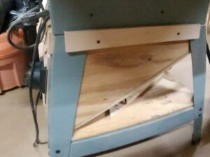
I have added an angled collector under my Table Saw (Contractor Saw) that catches the dust as it falls through the table.  I will be adding an enclosure for the back of the saw that surrounds the motor area. This will double as permanent outfeed support as well.

Table Saw Dust Collection Ramp

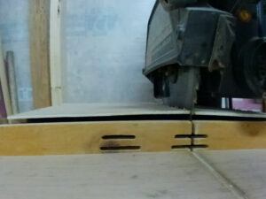
On the Radial Arm Saw, I cut slots in the fence and covered the area behind the fence.  A slot in the cover was cut for the saw blade. I am constantly amazed at the efficiency of this small change.Radial Arm Saw Dust Collection Hood

I added a 4” port to the back of the Router Table when I built it.  Eventually, I’ll be building a full Router Stand and include under the table dust collection but for now, this works to collect the amount of fine dust that is produced by the Router. It is a bit less effective at the larger dust but will collect at least 80% of the larger chips as well.

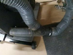
The Band Saw has a dual-port system.  I connected the two ports with a Y connector and some short hose.  This then has a port for the 4” dust collector hose. I’m not especially thrilled about the effectiveness of this arrangement.  Lots of coarse dust remains around the Bandsaw when I’m done using it.Bandsaw Dust Collection Port

The only remaining thing that I need to build is a box that contains a 20-inch box fan with recesses that can have filters quickly installed and replaced.  This will cycle the air in the shop several times an hour and pull the fine particles that are suspended in the shop into the filters.

A 20-inch box fan pulls roughly 540 CFM and with a shop that contains almost 11,000 Cubic feet, I should be able to cycle the air in about 20 minutes.  This will give me 3 changes through the box fan per hour. 6- 8 changes per hour is the recommended rate. If I find that I have fine dust still settling overnight, I will add a second box fan/filter arrangement.

The reason that I chose to use the box fan instead of a commercial unit is primarily the cost but in addition to that, I have seen this video from Izzy Swan that addresses the issue.

There is also a nice video that Jay Bates has done where he installs a furnace blower in a mobile base and surrounds the base with 4 air filters. (Mobile Air Cleaner Cart) This looks like a good solution that will move a lot of air.  If a furnace blower isn’t available, an air dryer can be used.  

What is the Best Dust Collector for a Small Shop?

There are lots of products available for small woodshop dust collection.  You can take the DIY approach or go with a commercial unit.

Of the commercial units that are available, I think the Shop Fox W1685 1.5 Hp unit has the best capacity for the price.

If you want to be a bit more DIY, get a 1 Hp blower with a filter bag(Shop Fox W1826),Single Stage Dust Collector connect it to a separator and mount the whole thing on a cart to wheel around the shop.

Last Word

When I got started with researching my Small Woodshop Dust Collection, I thought that a Shopvac was sufficient to do the job.  After some research, I now know that I was sadly mistaken.  I’d love to have a shop that is so clean you can eat off the floor but the nature of the material and the processes involved make that a pipe dream.  I’ll keep plugging away adding additional dust collection as I build out the shop.  For now, I have a good start and the shop stays relatively clean.  If I had a larger budget, I would implement a central collection system and run a conduit where I need. I think I have a pretty good solution for my current needs.

I’d love to hear about your Dust Collection adventures feel free to comment and ask questions in the comments below if you need help.

Building my Woodworking Work Tables

Building my Woodworking Work Tables

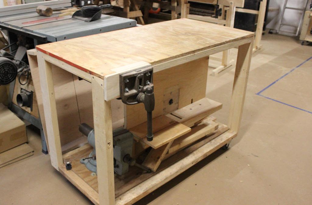
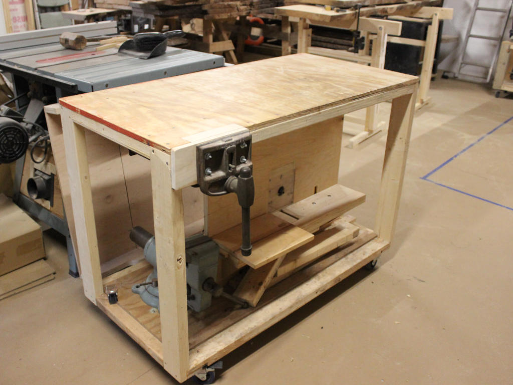
Woodworking Work Table- Rolling Outfeed Table

My first table is complete.  It holds up my Radial Arm Saw. Now it is time for building my Woodworking work tables.  Originally, I had decided that my first work table would be an actual Workbench. I have decided to defer this to a later time.  If in the future, I decide it is a necessary addition then I will build it at that time. For now, I’m going to focus on temporary tables and supports that are versatile and help me to determine the best flow through the shop.  I have limited space and am still working out the best way to use it to its full potential.

Types of Woodworking Work Tables

There are an amazing number of tables that can be useful in a woodshop.  You can have infeed tables and outfeed tables, you can have tables that roll around your shop or you can have a fixed workbench. You can create assembly tables even have temporary tables that you can set up for a specific use.

Workbench

As I mentioned above, I probably won’t build a workbench right away. However, I have done quite a bit of research into the various options that are available. Ultimately, a workbench is a fixture that will allow you to hold your work for various processes.  It needs a way to hold your work down and needs to be heavy to give a solid surface for you to work on without moving. It helps greatly if the top surface is flat and level to provide a reference surface for measuring and assembly.

The Roubo Workbench

Currently, the most popular bench style that I’ve come across is the Roubo bench. Also called the French Bench this design has descended from French craftsman. It’s characterized by a massive top typically of laminated wood, 4 by 4 trestle legs hold everything in place and a front vise and an end vise installed. Often there’s also a sliding deadman on the front. Dog holes extend across the front of the top to aid in work holding.

The Nicholson Workbench

The Nicholson Workbench has the same support structure as the Roubo Workbench but the top is a plank top. Two-inch thick planks replace the laminated top of the Roubo.  This lightens the bench but also requires that the underside of the top be supported by cross braces. The front and sometimes the back are additional planks with angled dog holes.  These come in handy for supporting long planks with either dogs or holdfasts.

The Nicholson bench is designed to be used with holdfasts so if you aren’t familiar with this type of holding process it can be a bit hard to understand how to hold your work. Mike Siemsen has done some great videos that explain how to use holdfasts with your bench.

Mike uses a viceless bench just to demonstrate that it can be done with holdfasts and some easy shop made jigs.

The Moravian Workbench

The Moravian Workbench is designed to break down and be relatively portable.  The top is typically a slab but may be laminated. The legs are splayed to provide stability and are connected with a tusk tennon that is removable.

The entire bench can be broken down in about 2 minutes and moved to a worksite or another work area.

Will Meyers from Wood and Shop demonstrates assembling the bench in this video. 

You can download plans from Wood and Shop if you want to build this bench.  https://woodandshop.com/moravianworkbench/

This will probably be the design that I use for my bench.  I wil add a split top and build it without a tool tray.  A Front Vice and a Wagon Vice will make workholding easy for both hand tools and power tools.

Infeed Table

For my shop, I needed to have a table next to the Radial Arm saw that can support the ends of long boards. This is commonly referred to as an infeed table.

I had a space 6 feet long next to the Radial Arm Saw.  There is an electrical box in the corner but I didn’t want to obstruct it with the table. It does provide an additional two feet of space before I hit the wall so I can put an 8-foot board on the infeed table with only a short length of board hanging over the end.

Infeed Table

As you can see this table has become my general work table. The top gets cleared off when it needs to perform its infeed duties.

I didn’t spend a lot of time building this table, I just banged it together with a three-quarter-inch piece of plywood on top and two by fours screwed together below the top. I added a shelf about 10 inches off the floor (So I can lift the table up with my lift cart in the event that I need to reorganize) The overall  height (35 inches)was determined by the radial arm saw table so that things can move off of the infeed table and onto the radial arm without changing the height.

Outfeed Table

With the radial arm saw infeed table complete,I needed to put together my table saw. I unboxed the table saw and assembled it then I realized that I needed to support longboards coming off of both saws. A portable outfeed table was a perfect choice. I designed a roll-around cart that would work at the radial arm saw as well as the table saw.

Since I designed the Radial Arm saw table to be exactly the same height as the Table Saw top, I was able to use a single cart for both machines. In a small shop, it pays off when you have one piece of equipment that will do double duty.

I wanted this cart to be a little bit more robust as I’ll be moving it around the shop I want to make sure that it doesn’t rack and fall apart. I did use two by fours to build the cart and chose 2ft by 4ft for the tabletop. I’ll probably  be using this or multiple operations so I fastened the wide edge of the two-by-four to the bottom of the plywood this gives me a two and a quarter-inch thick tabletop and still allows me to use my shorter clamps when I clamp things to the top.

Rolling Outfeed Table

I created two flat frames to hold the tabletop and the lower shelf using half-Outfeed Table Half-Lap Detaillap joints in the corners. For the uprights, I also created a 1/2 lap that overlaps the other half-lap joint for the top. I considered adding braces to the corners but so far that hasn’t been necessary. On the bottom, I added  4 casters two of these pivot and lock and the other two are fixed. This allows me to maneuver the table into any position I want and then lock it down to hold it in place. I will probably add fixed feet in the future and have casters that pivot up and lock to move the table.
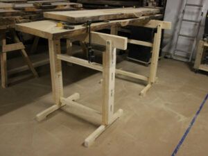
Saw Horses

It never hurts to have saw horses sitting around in the shop. When I was working in the carport, I created two nice strong fixed saw horses. This pair of saw horses were designed around a 2 x 6 top. I laid out a compound miter that was 10 degrees in two directions. This allows the legs to splay out to the sides and to the ends and creates a very stable sawhorse. It also allows an overhang at the end of the top board to provide me with a clamping surface. I made the sawhorses 42 in long and 32 in tall.  I screwed an apron made from pallet scraps about 18 inches from the top to keep the legs in position.

These saw horses work very nicely to support a 4 x 8 sheet of plywood and create a temporary assembly table. While I was still in the carport this became my work surface. When I was wiring the shop it became a very nice scaffold to work from and allowed me to get just high enough to reach the joists.

Adjustable SawhorsesUltimately I found that I need a second pair of saw horses. I sat down and designed  a pair of adjustable sawhorses. Even though I tried my darndest to make sure that all of the tables were at the same height, it turns out that some adjustability in temporary situations would come in handy. I designed these in a trestle style. They will adjust from 30 in tall to about 50 in. I can also replace the top 2 x 4 with a roller to help with infeed and outfeed tasks. I’ll do another post on the construction of these in the near future.
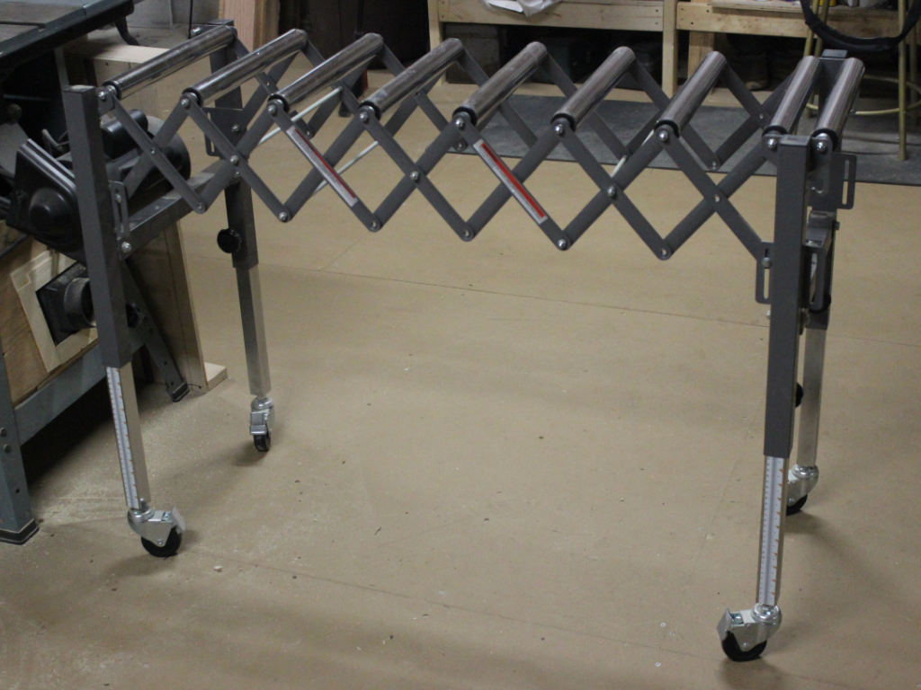
Roller Stand/ Roller Conveyor

The last piece of material handling equipment that I needed was a roller stand. I needed something I could feed material from the table saw and ultimately from the router table once it’s built. I waffled around a bit while trying to decide if I actually needed this or if I could build something that would fulfill the same purpose. I finally decided that I would purchase a telescoping roller conveyor.

Supermax Roller ConveyorThe roller stand that I settled for is a SUPERMAX TOOLS expandable roller conveyor. While this roller conveyor only expands to 50 in. The support it offers for long stock is well worth the purchase price.

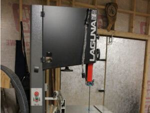
As an in-feed/ out-feed to my Laguna bandsaw, I found that the roller stand was not tall enough to meet the need. I wanted to be able to process long boards on the bandsaw but it needed to be 38 in tall to reach the table, the maximum height adjustability was 36 in so I needed to add some additional length to the lower tubes. I cut some Cherry stock to fit into the top of the tubes and added 6 in. to the height adjustment.

With all of these shop tables and material handling devices in place, I should be able to handle some large scale projects.  I’m looking forward to getting started with some smaller projects once I have completed putting together the adjustable saw horses.  It seems that I have a few board feet laying around (Cherry, Poplar, Live Oak, and Yellow Pine) and need to start reducing the pile with some projects.

First, I’m going to put together a Router Table so that I can do the joinery for the Adjustable Saw Horses.

Click the links below to view the tools and equipment outlined in this post:

Unboxing my Craftsman Radial Arm Saw

With power on to my shop, I’m finally to a point where I can start pulling my tools out of storage. The first tool that I’ll need is my radial arm saw. When I left Western New York, I boxed all my tools in plywood crates put them in a U-Haul trailer and dragged them down here to Tennessee. Once I had them here, they went directly into a storage unit where they have been sitting ,gathering dust.

Retrieving my Radial arm Saw

In the storage uniit I have a pile of wooden crates.  Inside the bottom one is my Lathe, the next on the stack is my Table saw and finally at the top is the Radial Arm Saw. The Table saw is the beast.  It probably has 150 lbs of stuff including the Bessemer Fence and of course the cast iron tables and steel wings for the saw itself.  This crate is HEAVY.

The radial arm saw was fairly light compared to some of the other tools in the storage unit, so I pulled it off the stack, I rolled it to the front of the Table Saw crate with a broom handle that was sitting in one corner and when I could reach the majority of the crate, I tiped it down to the transfer cart.  My steel toed boots came in handy as the cart shifted and I dropped the corner of the crate on my foot.  I should probably have enlisted help.

I rolled it out the door of the storage unit and onto the back of my truck.  The storage unit has nice ramps so I didn’t have to lift the crate onto the truck just backed it up and rolled the crate on. I have a lift cart in the shop already, so getting off of the truck was fairly easy, much easier than getting it off the cart and into the truck. I removed all of the screws that I used to hold the crate together then set the plywood off to the side for use in tabletops and other things. I’m a big proponent of reuse and recyle so the plywood will come in handy for shop carts and tool bases.

At this point, I decided to pull the lathe and table saw out of storage as well. They needed to be moved and I just happen to have a friendly helper to get them onto the truck. Thes two crates were large and heavy so we made two trips.  The table saw was heavy enough that we didn’t want to pick it up a second time.  I opened the crate right in the truck and unloaded the pieces.  Much easier on the back.

Unboxing my Craftsman Radial Arm Saw

Unboxing the radial arm saw was pretty easy. It was just a matter of removing about 60 screws. I was pleased with how it had travelled, it was precisely where I had expected it to be inside the crate. Nothing appeared to have shifted and no damage had occurred.  When I put it in the Crate, I removed the table and screwed the base down to the bottom of the crate.  I made sure that the carriage was tightened down and then I secured that in place with a piece of wood screwed to the sides of the crate.

I had one small problem though, the table for my radial arm saw did not come with me. In New York I had a plywood frame with a lower shelf. The front had to two-by-fours going all the way to the ground and the back had a pair of wheels. it was easy to pick up the front of the radial arm saw and roll it to where I needed it and then set it back down. I opted for a fixed-base this time. I’ll be building a table next to the radial arm saw so a fixed position will work very nicely.

A Table for the Radial Arm Saw

I decided that I wanted the top of all my tools in my tables to be at the same height. I chose 35 in to be the height that I use throughout the shop. I recall that the table saw was already 35 in tall so if I had to use the radial arm saw table to support the end of a long work piece I could do so. I had a bunch of two-by-fours that were left over from building the shop so I found the straightest ones possible and opted to use the plywood from the crates as table tops. The lift table when fully retracted is 9 1/2 inches off the floor so I chose to make the lower shelf slightly above that height so I could slide the lift cart in and move things as I needed.

To build the base for the radial arm saw I just cut for two by fours three quarters of an inch short of where I needed them and then screwed the top on and reinforced it with cross members made from the same two by fours. I repeated the process for the lower shelf and dropped a piece of scrap plywood on the lower two by fours.

Install and Set Up The Radial Arm Saw

To install the radial arm saw, I drove mounting holes for lag bolts and screwed it down to the table. I had to add some shims to make sure that everything was level. I took another piece of three-quarter inch plywood and cut it to create a working surface for the top of the saw table. It’s important when you’re installing the saw table to make sure that the back of the top lines up with the zero mark on the arm of the radial arm saw. The mounting holes that hold the top to the radial arm saw base or slotted so as long as you get it close you can adjust as needed. When that top was installed I added another quarter inch piece of Luan plywood to the top as a sacrificial table top. It’s attached with tiny Brad’s on the corners so that it doesn’t warp but the table top stays in place. I can remove and change out the sacrificial top easily when it gets too cut up to use.


Set up the Radial Arm Saw

Finally, I needed to adjust the radial arm saw and make sure that it was square to the fence.

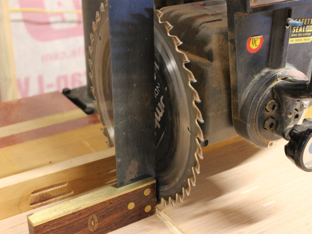
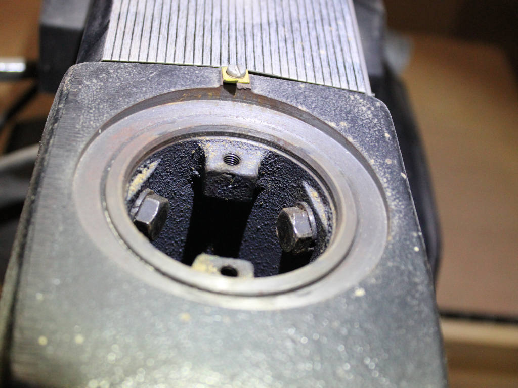
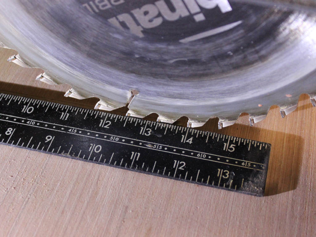
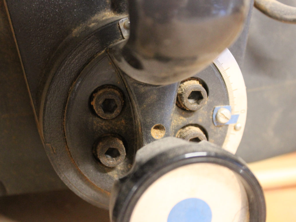
The first focus was to square the blade to the table. This is pretty simple, There are 4 Allen bolts on the front of the handle.  Loosen these and the tilt of the saw blade can be adjusted.  I used a square against the table and between the teeth of the saw blade and squared the tilt.  Holding this in position, I tightened the Allen Bolts. You need to make sure that the square is up against the flat of the blade and isn’t registering on the teeth of the blade.  Tilting the square will enable it to fit between the gullets of the saw blade and give an accurate reading.


Next the Arm of the radial arm saw needs to be square to the fence.

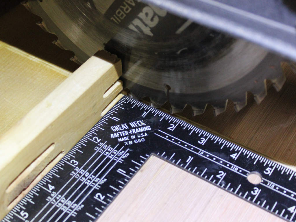
The adjustment of the arm is done from the pillar in the back.  there are two Bolts at the top of the column that hold the arm to the pillar.  Loosening thes will allow som back and forth adjustment.  Loosen the bolts and then lay a carpenter square against the fence.  adjust the arm so that the  blade of the saw just touches the square at the fully back position and at the fully forward position.  Retighten the bolts and check to make sure the adjustment is still accurate.


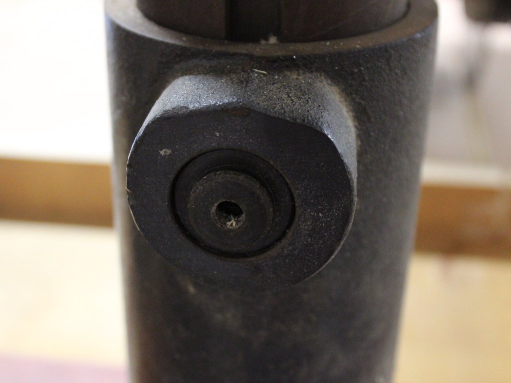
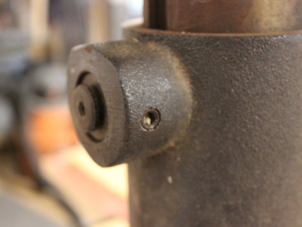
Finally, there is a wedge on the back of the saw pillar that controls how much back and forth play is in the arm.  There are two set screws on either side of the wedge and another on the back to adjust in and out.  loosen the two side screws and then adjust the wedge in until it bottoms out then back it off 1/2 turn.  This sets how difficult it is to adjust the angle of the arm. Tighten the side screws until the play has been removed.  These screws oppose each other so loosen one side and tighten the other until you have the play removed.


I spent some time making sure that all of the adjustments for the radial arm saw were square and true. Given the age of this radial arm saw there’s still a bit of play in the main pillar but it works very nicely for rough cutting.

Next up I needed to create an infeed table. This will double as a general workspace with a little bit of storage underneath.

Woodshop Wiring

In my last post, I talked about putting up the building. My next task was to get electric power to the building and to wire the inside.

Electrical Permits Start the Process

To start this process, the first thing that I needed to do was get electrical permits. Our local utility has an office that accepts permit applications during a small window of time (7:30-9 AM). I braved the commuter traffic and paid my fee with the local utility. I also set up an appointment with a site representative to come out and discuss where we’re going to put the line that provides power to the shop. After going around and around several times we finally settled on a second meter on the house that would provide separate electrical service to the shop.

Supply Line Design

The power to the shop would go through a meter mounted on the house through electrical conduit for about 75 ft mounted above ground on the wall of the house. Then the conduit would go underground across the yard for another 75 ft.  and emerge on the corner of the shop. I was a bit surprised that the inspector said that he needed to have ground wires run at the house and at the shop it’s my understanding that most municipalities want a single ground and then a ground wire run out to the shop. Since this gentleman was going to be doing the inspection I did it to his specification.

To ensure that we had all the capacity we needed I settled on a 200-amp service. This way we can run several 220-volt circuits as well as several 120-volt circuits inside the shop and have plugs where we need them and excess capacity. I really wanted to run copper wire from the electrical box across the hundred and fifty feet to the shop but it’s just not available. I had to settle for 4/0 aluminum cable. The conduit was 4-inch electrical conduit suitable for above-ground and underground installation.

Conduit on end of houseI started by installing the meter box on the side of the house adjacent to the currently installed meter. I was a bit surprised when the meter box was considerably shorter than the one next to it (more on this later).
My plan was to run the conduit from the meter box down the wall about two feet across the wall, another four feet up to the top of the wall and around the corner. Then running across the garage door,  around another corner and then down into the ground. Once I was in the ground I’d run it through a trench along the rest of the side of the building and out across the lawn until I got to the shop. This would avoid the garage opening and get me past the Well and all of the water lines that came into the house next to the Well.

Installing the Conduit

I laid out all the conduit and mounted it to the wall. To mount it I use lead anchors that take a quarter inch lag bolt. I ran the lag bolt through a conduit clamp. Each anchor had to have a quarter-inch hole drilled in the brick and then the anchor was installed and the conduit clamp installed with a washer into the anchor. At this point I didn’t install the wiring I just wanted to have all of the conduit sized, mounted and ready to receive the wire.

When I had all of the conduit in place around the garage door and across the side of the house it was time to go get a ditch digger. I stopped by my local United Rental and had them supply me with a trenching tool. This also goes by the name of Ditch Witch. For those of you that are not familiar with this tool, it’s a large rotary disc powered by a gasoline engine. It cuts a 2 ft deep channel in the ground about 6 inches wide and then has an auger on the side that piles all the dirt removed next to the hole.

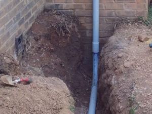
Conduit Entering Ground

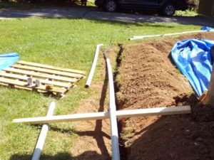
The ditch that I had to run crossed about 45 ft of lawn then turned 45 degrees and ran along the house for about another 35 ft. I started with a shovel, digging two 2 ft deep holes at either end of the run. I installed conduit and put on the 90-degree turn that would connect to the long section of the conduit in the trench. For this layout, I laid down the long straight pieces of conduit and identified where exactly I needed to make the 45-degree turn. Then I fired up the trencher and started next to the shop cutting a trench across the main section of lawn. I overshot the trench at both sides of the 45-degree turn to try and keep the dirt out of the trench where I was changing directions.

I reoriented the trencher to move across the side of the house and was moving very well for about 15 feet. Then I started to hit construction debris. It appears that the installer of the building had just tossed a bunch of bricks and rock around the foundation of the house and then covered it with dirt. It took me about 45 minutes to cut across the lawn and another three and a half hours to cut the edge along the house.

When I finally got close to the end I had to reverse the direction of the trencher because I was too close to the wall. About two feet after I started cutting back towards the main trench a fountain of water erupted from my trench. It appears that the waterline feeding the house was not where it was expected to be. If I had known that the water line was there, I would have continued my above ground conduit along the side of the house as well. Instead, I got to spend a day and a half repairing the waterline.

Pulling Wire Through ConduitMy next task was to lay out all the conduit inside the trench and prepare it for installing the wire. The water line turned out to be very problematic as I needed to run the wire through the conduit around the house and then connect the conduit underneath the waterline. This meant that I couldn’t install all the wire and all the conduit and just lay it into the trench. It took considerably longer to work around the waterline.
To complicate matters it started to rain. Not just a little bit of rain here and there but torrential downpours. Each day for a week we received about 3 in of rain a day. My trenching job was on hold while we waited for the rain to stop. I covered the trench with several tarps and anchored them down to keep them from blowing off the trench and to keep the water out of the trench. Did I mention that I’m working in clay soil. Every time I stepped on the dirt my feet gained 2 lb of sticky slimy clay.

Interior Shop Wiring

While it was raining I turn my attention to the inside of the shop. I had decided to use 5 circuits for the 120 volt supply lines. The first circuit supplied the exhaust fan and the lighting for the shop. This circuit had 3 wall switches for each of the devices. The remaining four circuits provided power to a number of plugs along the walls of the shop. I also added 3-30 amp 220-Volt circuits for various shop equipment and one 50 amp 220-Volt circuit for a plasma cutter that we will have attached to our CNC unit to make decorative metal.

The five 120 volt circuits are all wired with 12 gauge wire. This is so that we can connect 20 amp duplex sockets and not worry about overloading the circuits. Each one of these circuits has a ground fault circuit interrupter plug first in line. By putting the GFCI first it protects the entire circuit. The shop is classified as a garage so GFCI circuits are required by code.

Each of the three 30 amp 220-volt circuits are wired with 10 gauge wire. I have the band saw connected to the first 220-volt circuit. The second 220-volt circuit will be for the air compressor. An air compressor is required for the plasma cutter to provide shield gas. The third 220-volt circuit will be for a Planer or Jointer that will be purchased in the future.

The 50 amp 220-volt circuit is dedicated to the plasma cutter. This is wired with 6-gauge wire. It will be dedicated specifically to the plasma. If I find that I need to weld I will probably use gas. I have some experience welding with oxy-acetylene and it’s my preferred method. If we do end up getting an arc welder, I can plug this into the circuit for the band saw and weld out in front of the shop. The flooring in the shop is not fireproof so welding needs to be done outside.

It took several days for the rain to stop and while that was happening I was able to get all of the wiring in place and prepare the electrical panel inside the shop.

Electrical Inspections

Finally, the rain stopped and I was able to run the wire from the meter box on the side of the house through all the conduit and out to the shop. I took this opportunity to glue up all the conduit and then I called the inspector to come out and bless my trench. Apparently, they need to verify the specifications of the trench to make sure that it was two feet deep. Once he gave me the okay I was able to fill in the trench.

With the wiring installed I was able to complete the wiring to the electrical panel and install the circuit breakers and all the duplex outlets and 220-volt outlets. Then I had to call the inspector back and get the final inspection done on the shop.

The inspection was somewhat of a letdown as he noticed that I had installed a 100 amp meter box on the side of the house. So, I had to tear the 100 amp meter box off the wall and install a 200-amp meter box. Fortunately, the additional length of the 200-amp box provided me with sufficient wire lengths to make the connections. This really was a minor inconvenience. The inspector was doing an inspection on a house just up the road from me so the next day he stopped on his way out to the other inspection and gave me a green light.

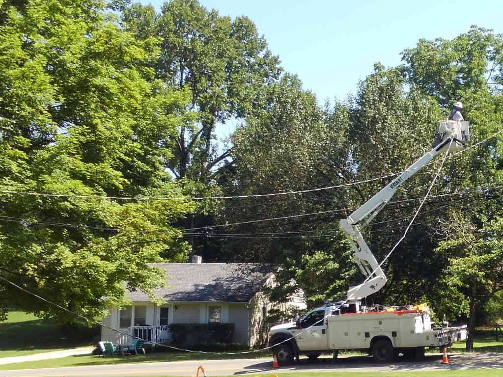
The final inspection was the trigger to have the Utility company come out and install the wiring from the pole across the street to the meter box. they arrived two days later with a cherry picker and enough wire to make the final connection. It took them about a half an hour to install the connection from the top of my riser across the street to their Transformer. Very quick and very professional.

Power Company Connection

I now had power to the shop.

I went out to the shop and flipped on the main breaker, plugged in a light to make sure everything was working and found …nothing. I pondered a bit on what might be wrong and then I realized the ground fault circuit interrupters needed to be reset the first time power was applied. Once I reset the GFCI plugs everything came on and was fully operational.

Yeehaw!  I have power!

The next phase of this project is to get all of my tools out of the storage unit and into operation.  Follow along as I unpack and calibrate my radial arm saw, my table saw, my lathe ( which doesn’t need calibration), Dust collection, etc. and in general get my shop operating and ready-to-use.

Stay on Top with Woodworking Warrior

Join the mailing list to receive the latest news and updates from us!

You have Successfully Subscribed!

Pin It on Pinterest