Beginner’s Guide To Woodworking
If you’re curious about the craft of woodworking, you’re in good company. Across the globe, people are discovering the satisfaction that comes from transforming a simple piece of wood into something beautiful and functional. Let me guide you, in this beginner’s guide to woodworking, through the fundamentals to get you started on this rewarding path.
This isn’t just about learning to hammer and saw; it’s about the deeper joy of creating something with your own two hands. Whether you’re aiming to build furniture, craft small trinkets, or simply enjoy a new hobby, woodworking can offer you that sense of accomplishment.
In my experience, safety is the cornerstone of any successful woodworking practice. Consider protective gear, proper tool handling, and workshop safety measures as your allies, not just rules to follow. It only takes a moment of inattention to ruin your day, your week, or your piece. Working safely will not only ensure your well-being but also improve the quality of your work.
As you start this journey, you’re going to find out about various sources of woodworking ideas, from classic patterns to innovative designs. Inspiration is all around you, from online communities to woodworking magazines, and I’ll point you where to look.
Setting Up Your Workspace: The Foundation of Craftsmanship
When you’re just starting with woodworking, having a dedicated space to practice and create is as crucial as mastering the skill itself. You’ll discover that a well-organized shop can make a world of difference in both the enjoyment and safety of your woodworking journey.
Choosing the right location is your first step. Your workspace doesn’t need to be large, but it should be well-ventilated and dry to protect you and your materials. If it’s a shared space like a garage, make sure you can keep it organized and secure when not in use.

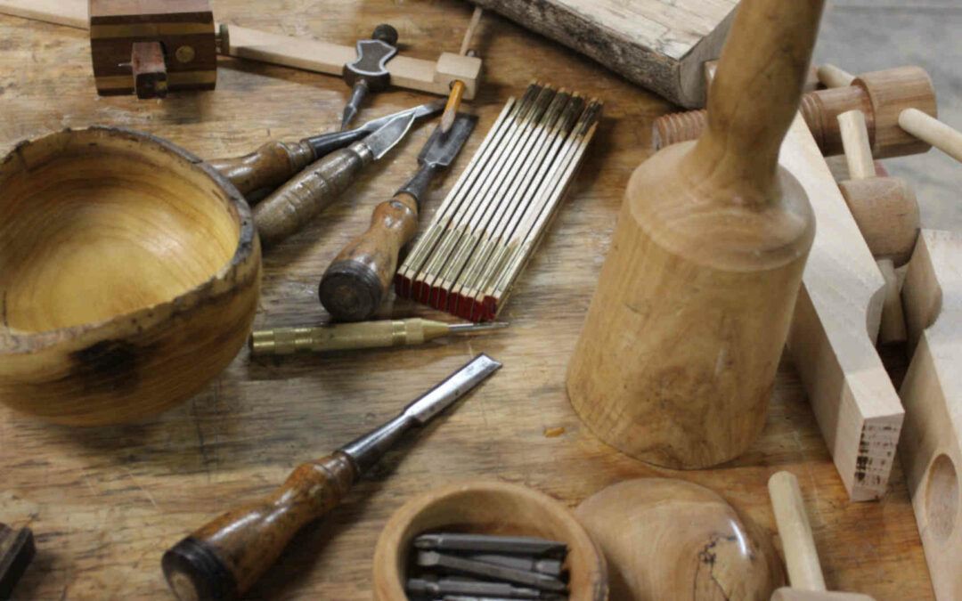
In my opinion, investing in essential tools is paramount for getting off to a good start. Begin with purchasing quality basics: a reliable saw, a smooth plane, and sharp chisels. Quality doesn’t have to break the bank—look for well-made pre-owned tools or brands with a solid reputation. If you buy cheap tools, you will spend more in the long run. Buy the best you can when you are able.
Organizing your workspace is about more than just neatness; it can quite literally prevent accidents. Clearly label storage for tools and materials, and ensure that common tools are within easy reach. Spending a little time planning your layout can pay off in a big way, making your workflow smoother and safer.
Lastly, don’t think you need the fanciest setup right out of the gate. Start with a sturdy workbench that suits your height to avoid back pain, add good lighting, and you’re well on your way. You can always adjust your approach down the road as you get more invested in the craft.
Mastering the Basics: Key Skills for Aspiring Woodworkers
Have you ever watched a skilled woodworker and wondered if you could ever match their prowess? Well, becoming proficient in this craft is a mix of understanding core techniques and consistent practice. I’m going to walk you through the key skills that every beginner should focus on.
Measuring and marking accurately are the cornerstones of successful woodworking. Remember the old adage, ‘measure twice, cut once’? It’s timeless for a reason. Improper measurements can lead to wasteful mistakes.
Here’s a quick little anecdote for you. Way back in the ’80s my uncle was building a vacation cottage in Florida and I was invited to stay for the summer. The cottage was rustic, with plywood floors, and the second-floor stairway was a ladder. We had electricity and running water but that was about the extent of it. They brought a bed in and we put it upstairs but there were no shelves or any furniture of any kind so I needed a set of shelves. I went down to the Big Box store and bought some 2x4s and some plywood and figured I’d make myself one. I cut 2 x4 inch slots out of the corners of the plywood pieces and nailed some 2x4s underneath them but when I went to put the 2x4s in the slots they were not big enough. I learned about nominal versus actual measurements that day. A 2×4 is not 2 in x 4 in it is three and a half by one and a half. All my uncle had to say was “Measure twice, cut once”.
Joinery is where your projects start taking shape, quite literally. From simple butt joints to more complex dovetails, each has its place, and learning when and how to use them is a game-changer. It affects the durability and aesthetics of your finished piece.
You also need to know your materials. The type of wood you choose can influence the project’s look, feel, and lifespan. Softwoods are generally more user-friendly for beginners, while hardwoods might require more advanced tools and techniques.
Finishing your project with sanding, staining, and sealing can turn ‘decent’ work into ‘stellar’ results. These steps are crucial for the look and longevity of your work, and they’re worth getting right from the start.
These skills aren’t just about reading and theory. They require you to roll up your sleeves and get some sawdust on them. Start with some small projects like a birdhouse or a simple box to get a feel for the process.
Navigating Challenges: Common Mistakes and Solutions
When you start diving into any new hobby, especially one as intricate as woodworking, there’s a steep learning curve. You’re going to find out about several stumbling blocks along the way. But don’t worry too much about that; it’s all part of growing into a skilled craftsman.
One of the biggest issues for novices is underestimating the importance of precise measurements. Use tools that are accurate to start with and you will get better results. If you want to create pieces that fit together seamlessly, it’s critical to measure twice and cut once – it’s a cliche for a reason. A hair’s breadth can make a difference between a project that fits perfectly and one that’s askew. So my advice here is to slow down and double-check those numbers before making any cuts.
Another common mistake is choosing the wrong wood for your project. Hardwoods and softwoods behave differently and picking the wrong type can lead to issues down the line with durability, appearance, and workability. I recommend starting with softer woods that are more forgiving and easier to work with, like pine or cedar. In either case, use dry wood. Wood moves as moisture is absorbed or evaporates. Dry wood is stable wood.
There’s always a chance of equipment mishaps, which can include a dull blade causing rough cuts or poor maintenance leading to inaccurate measurements. Your tools are your best friends in the shop, so keep them sharp and in good working order. And if things do go sideways, a calm assessment and an internet search or two can often provide a fix.
I’m going to touch on an underrated aspect: patience. Processes in woodworking can be time-consuming and sometimes temper-testing. Rushing can often make mistakes more likely and lead to frustration. It’s essential to remember that woodworking is a craft that improves with time and that your first attempt doesn’t need to be your last.
In the end, mistakes are invaluable learning opportunities. Every chip of wood and every sawdust pile is a story of challenges faced and knowledge gained. I encourage you to share your experiences with the woodworking community – forums, social media groups, and local clubs can be tremendous resources. Now let’s look ahead to when your skills are more developed, and talk about how you can share your work and keep evolving in your woodworking journey.
Creating and Sharing: Beyond the Basics
You’ve laid the groundwork, acquired the skills, and faced down challenges on your woodworking journey. Now what? It’s time to spread your wings and explore just how far your new talents can take you. This isn’t just about making things, it’s also about personal growth and community.
As your confidence grows, you’re going to find out about intricate techniques like inlays, dovetails, or even woodturning. Each of these skills opens up new possibilities, letting you tackle more complex projects or put your stamp on classics. Choose something that resonates with you and challenges you.
But woodworking is not solely about what you make—it’s about the connections you forge. Sharing your creations can bring a sense of accomplishment and joy. Whether it’s presenting a handmade gift, selling pieces at a local craft fair, or contributing to community projects, your work has the potential to touch the lives of others.
Don’t forget to document your journey. Taking photos of your projects provides a visual history of your progress and can inspire others. Social media platforms are perfect for connecting with fellow woodworkers, sharing tips, and showcasing your masterpieces.
Lastly, remember that learning is a lifelong journey. You can always adjust your approach down the road by attending workshops, signing up for classes, or diving into books dedicated to woodworking. Every piece you create is a learning opportunity and a step towards even greater achievements in woodworking.
I hope that you’ve enjoyed this beginner’s journey into the world of woodworking. Keep building, keep learning, and most importantly, keep sharing your passion with the world.
I’ve been playing around as a hobbyist Woodworker for many years. I have a few tips and tricks up my sleeve. Feel free to look around at this website and see if any of my projects give you a bit of incentive to start your own journey. I especially like to create novel tools and fixtures that make my life easier. I know that you can buy most everything these days but there is a certain pride to create something that you can use all the time to make your life easier in the shop.


 As a long-time Woodworker, I've built a variety of large and small projects. I've learned to use the tools available to me to get the job done.
 I hope you enjoyed this short project. I know that I’ll use it often.
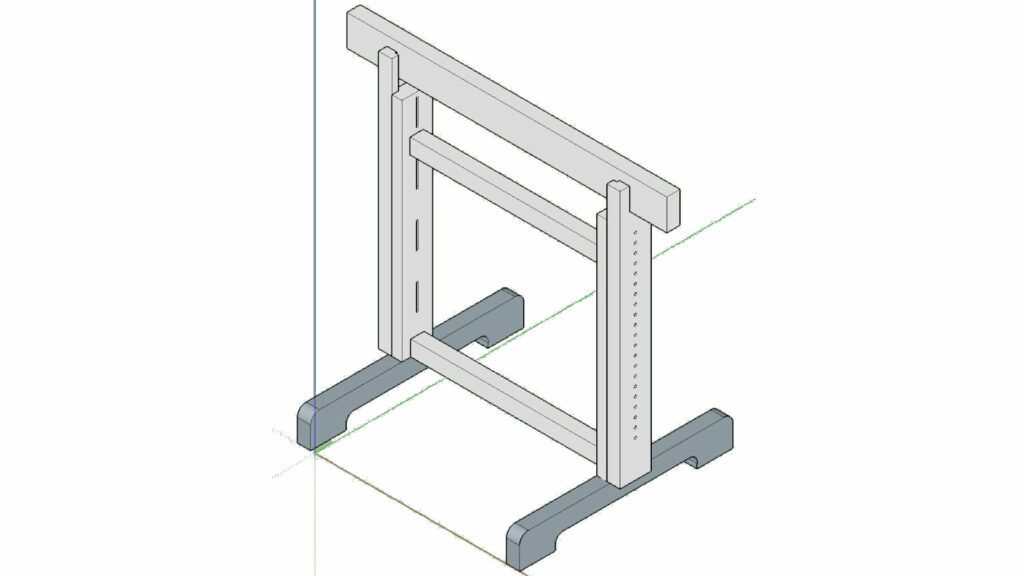
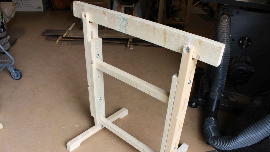
It will come in handy for my next project. I’m going to be creating some adjustable sawhorses.
Feel free to comment below on this project or any other that you see on this site.
I hope you enjoyed this short project. I know that I’ll use it often.
It will come in handy for my next project. I’m going to be creating some adjustable sawhorses.
Feel free to comment below on this project or any other that you see on this site.